Flow Control: what is it and how does it work in OSI Model
Our lives become increasingly convenient since the booming of the computer technology. Since we rely on the computer network more, it is better for us to understand of underlying technologies that provide us with these services. The OSI model is a conceptual model which contains seven layers with variety functionalities. The topic of this essay concentrates on the flow control in OSI seven layers model.
To begin with, we need a brief introduction of OSI model and the basic function of each layer in it. As we all known, there are seven layers in OSI model, from the bottom level, they are: Physical Layer, Data Link Layer, Network Layer, Transport Layer, Session Layer, Presentation Layer, Application Layer. The following picture (Description of OSI layers, retrieved from Wikipedia) clearly shows the functions of each layer separately. In addition, in data communications, flow control is the process which happens between two nodes and tells the sender how much data it can transmit before it must wait for an acknowledgement from the receiver.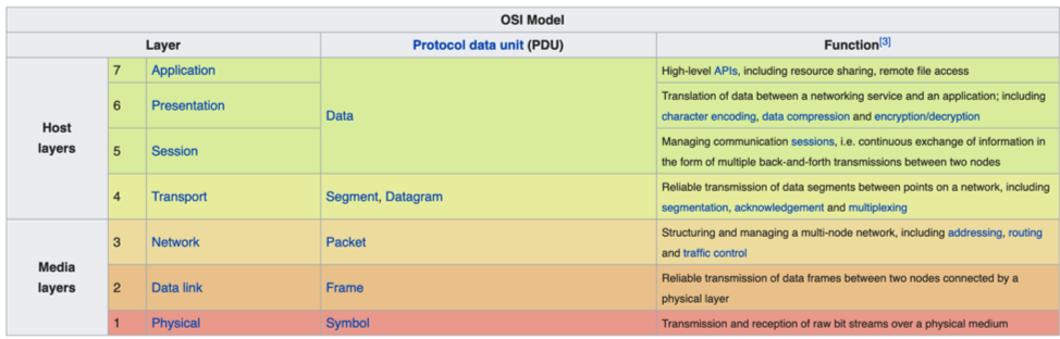
As we can see, the function of each layer is different from each other. According to Alani (2014), Physical Layer is not responsible for flow control in general. Data Link Layer may provide flow control and error control “on the wire”. Network Layer provides flow control between routers by ICMP (Internet Control Message Protocol), the end terminals usually do not use the network layer barely, and IP(Internet Protocol) does not provide flow control. Transport Layer, there is a more specifically TCP (Transmission Control Protocol) provides flow control by a backtracking algorithm while UDP (User Datagram Protocol) does not, TCP has various flow and congestion avoiding protocols, such as TCP Vegas.
Flow Control Mechanisms
According to Karunkuzha (2013) and Tomar (2013), the basic flow control mechanisms are: Stop-and-Wait, Go-Back-N automatic repeat request (ARQ), and Selective-repeat ARQ. As to the Stop-and-Wait, this mechanism forces the sender after transmitting a data frame to stop and wait until the acknowledgement of the data frame sent is received. The disadvantages of the Stop-and-Wait are obvious. The drawback includes that there is only one frame that is sent and waiting to be acknowledged. Therefore, it is not a good use of transmission medium. On the other hand, the last two methods based on a basic algorithm called “Sliding Window”. In this mechanism, multiple frames would be in transition while waiting for acknowledgement, and the usage efficiency of transmission medium is improved.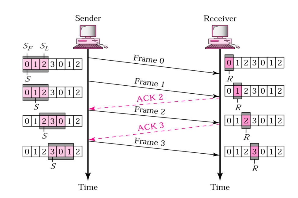
In Go-Back-N ARQ mechanism, data frames from a sender are numbered and counted sequentially. Since this method is based on “Sliding Window” algorithm, the window cannot be infinite. There must be a limit and we include the sequence number of each data frame in the header. In the following picture, it can be tell that how the mechanism works. In the sender, the window slides to include new unset frames when the correct ACKs(acknowledgement) are received. And in the Receiver, it always looking for a specific frame to arrive in a specific order. And usually, the sender sliding window can be set a range from 0 to 2^m, and the receiver sliding window size is always 1. The Go-Back-N ARQ is efficient, and powerful to handle exceptions, such as damaged, lost, or delayed ACK.
In addition, there is another mechanism called Selective Repeat ARQ. Even though the Go-Back-N ARQ simplifies the process at the receiver side. In receiver, it only keeps tracking one variable, and it does not store those out-of-order frames as buffer. Those data frames are simply discarded. However, it is a bad use of its bandwidth, and it also slows down the transmission. The following picture shows how the Selective Repeat ARQ handles lost data frame with sending NAK (negative ACK).  In Selective Repeat ARQ, only the damaged data frame is resent to receiver. It could make the fully use of bandwidth, but it requires more complex processing at the receiver. It defines a negative ACK to report the sequence number of a damaged or lost data frame before the timer expires.
References
Alani, M. (2014). Guide to OSI and TCP/IP Models.
Karunkuzha, D., & Tomar, D. (2013). Traffic Flow Analysis Based Flow Control Mechanism for next Generation Network. Information Technology Journal, 12(7), 1439-1443.
Wong, W., & Zhu, Tingshao. (2014). Computer Engineering and Networking : Proceedings of the 2013 International Conference on Computer Engineering and Network (CENet2013).
Pictures are retrieved from website:
https://serverfault.com/questions/545655/which-layer-is-responsible-for-flow-control
https://en.wikipedia.org/wiki/OSI_model
https://stackoverflow.com/questions/45301576/flow-control-in-data-link-layer-vs-flow-control-in-transport-layer